TFT LCD Manufacturing Process Engineering
A comprehensive overview of the intricate processes behind modern liquid crystal display production, including insights relevant to lcd screen replacement technologies.
Introduction to LCD Manufacturing Process
The manufacturing of Thin Film Transistor Liquid Crystal Displays (TFT LCDs) involves a highly sophisticated, multi-step process that combines precision engineering, advanced materials science, and cutting-edge automation. These displays have become ubiquitous in modern electronics, powering everything from smartphones and laptops to televisions and industrial monitors. Understanding this complex process is essential for professionals in the field, including those involved in lcd screen replacement services who need to appreciate the technology they work with daily.
TFT LCD production can be broadly divided into six major stages, each with its own set of intricate subprocesses requiring specialized equipment and controlled environments. These stages include array fabrication, color filter manufacturing, cell assembly, module assembly, and final testing. Each stage must maintain extremely high precision, as even microscopic defects can render an entire display non-functional.
The entire manufacturing process takes place in ultra-clean facilities known as cleanrooms, where airborne particles are strictly controlled. Class 100 cleanrooms (fewer than 100 particles larger than 0.5μm per cubic foot of air) are standard, with critical processes requiring even higher standards. This level of cleanliness is essential because a single dust particle can cause a permanent defect in the display, which is particularly problematic for lcd screen replacement operations that require pristine components.
Over the years, TFT LCD manufacturing has evolved significantly, with continuous improvements in resolution, brightness, power efficiency, and production yield. These advancements have not only enhanced display performance but have also made lcd screen replacement more accessible and cost-effective for consumers and industries alike.
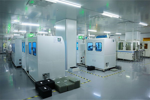
A modern cleanroom facility where TFT LCD manufacturing processes take place, maintaining strict environmental controls essential for producing high-quality displays used in lcd screen replacement applications.
Array Fabrication Process
The array fabrication process is the first and most complex stage in TFT LCD manufacturing, involving the creation of thin film transistors on a glass substrate. This process is analogous to semiconductor manufacturing and requires similar precision and technology. The quality of array fabrication directly impacts the display's performance and durability, which is crucial information for professionals involved in lcd screen replacement who must assess display quality.
Substrate Preparation
The process begins with ultra-thin glass substrates, typically 0.5mm to 0.7mm thick, made from aluminosilicate glass for its heat resistance and dimensional stability. These substrates undergo rigorous cleaning using a series of chemical baths and ultrasonic cleaning to remove any contaminants. This step is critical because even minute impurities can affect transistor performance, potentially leading to premature failures that necessitate lcd screen replacement.
Deposition of Thin Films
Multiple layers of thin films are deposited onto the cleaned glass substrate using techniques such as chemical vapor deposition (CVD) and sputtering. These layers include:
- A gate metal layer (usually molybdenum or aluminum)
- A gate insulation layer (typically silicon nitride or silicon oxide)
- An active layer (amorphous silicon or polycrystalline silicon)
- Source and drain electrodes
Each deposition step requires precise control of temperature, pressure, and chemical composition to ensure uniform film properties across the entire substrate. These layers form the basis of the TFT structure that controls each pixel, making their quality essential for avoiding issues that might later require lcd screen replacement.
Photolithography and Etching
Photolithography is used to pattern each layer. This involves applying a photosensitive resist, exposing it to ultraviolet light through a photomask, and developing the resist to create the desired pattern. The exposed areas of the thin film are then removed using wet or dry etching processes.
This patterning process is repeated for each layer, with alignment accuracy measured in micrometers. The complexity increases with higher resolution displays, which require smaller and more densely packed transistors. For lcd screen replacement specialists, understanding this complexity helps explain why higher resolution displays typically cost more to replace.
Cross-sectional diagram of a TFT array structure, illustrating the various layers and components that must be precisely manufactured to ensure display functionality, knowledge that aids in lcd screen replacement evaluations.
TFT Array Testing
After fabrication, each array undergoes rigorous testing using automated probe systems. These tests check for defective pixels, short circuits, and other electrical anomalies. Displays with excessive defects are rejected, ensuring only high-quality panels proceed to subsequent stages. This quality control step is crucial for minimizing lcd screen replacement rates due to manufacturing defects.
Advanced testing systems can detect even microscopic defects that might affect long-term reliability. The testing process has become increasingly sophisticated alongside display technology advancements, helping maintain high standards even as pixel densities increase dramatically.
Color Filter Manufacturing Process
The color filter manufacturing process creates the RGB (red, green, blue) color layer that, when combined with light and TFT control, produces the full color spectrum visible on LCD screens. This process is critical for display quality, as color accuracy and uniformity directly affect user perception. For lcd screen replacement professionals, understanding color filter technology helps in matching replacement screens to original specifications.
Substrate Preparation for Color Filters
Similar to array fabrication, color filter production begins with clean glass substrates. These substrates must meet strict flatness requirements to ensure uniform color reproduction across the display. Any irregularities can cause visible artifacts, which is particularly problematic for high-end displays where lcd screen replacement must maintain the original visual quality.
Color Resist Application and Patterning
Each color (red, green, blue) is applied in separate photolithographic processes:
- A color-sensitive resist material is applied uniformly across the substrate
- The layer is exposed to UV light through a mask defining the pattern for that color
- The unexposed areas are removed during development
- The process repeats for each of the three primary colors
Modern processes use high-precision alignment systems to ensure each color's pixels align perfectly with corresponding TFTs in the array substrate. Misalignment would cause color shifts and reduced image quality, potentially leading to customer dissatisfaction and increased lcd screen replacement requests.
Black Matrix Formation
A black matrix (BM) is applied before the color filters to prevent light leakage between pixels and improve contrast. Typically made of chromium or organic black materials, the BM is patterned using photolithography to create a grid that defines individual pixel boundaries.
The quality of the black matrix directly impacts display contrast ratios. Poorly formed BM can lead to light bleeding between pixels, reducing image quality and potentially necessitating lcd screen replacement in critical applications.
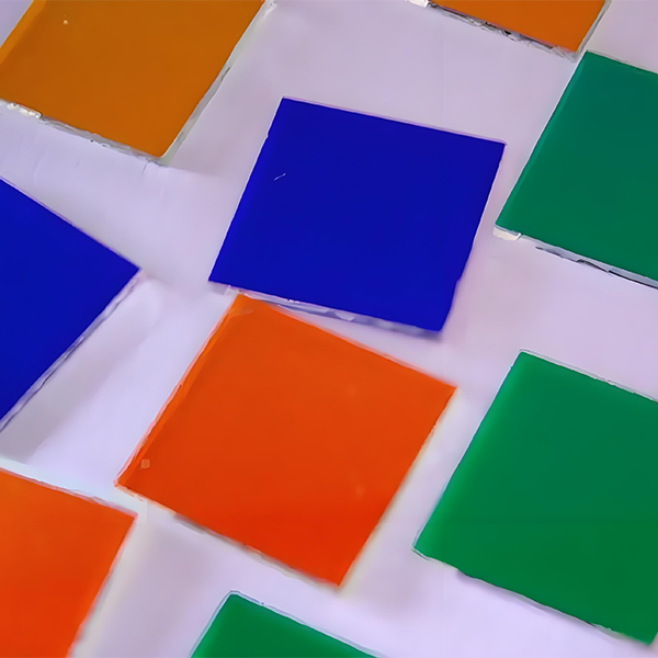
Microscopic view of color filter pixels, demonstrating the precise arrangement of RGB elements and black matrix that are critical factors in display quality assessments during lcd screen replacement.
Overcoat Layer and Quality Control
After applying all color layers, an overcoat layer is deposited to protect the color filters and provide a flat surface for subsequent cell assembly. This layer is carefully polished to ensure uniform thickness and smoothness.
Color filter substrates undergo rigorous testing for color accuracy, uniformity, and defects. Automated optical inspection systems check for pinholes, foreign particles, and color variations. These quality checks are essential for maintaining consistent display performance and reducing the need for lcd screen replacement due to visual defects.
LCD Cell Assembly Process
The LCD cell assembly process brings together the array substrate and color filter substrate to form the basic liquid crystal cell. This stage transforms two separate components into a functional display element capable of light modulation. The precision of cell assembly directly affects display performance, making it a critical consideration for lcd screen replacement where proper functioning is paramount.
Alignment Layer Application
Both the array and color filter substrates receive an alignment layer, typically a polyimide material. This layer is applied using a spin-coating process to ensure uniform thickness, then cured at high temperatures.
The alignment layer is then rubbed with a fine cloth in a precise direction. This rubbing creates micro-grooves that guide liquid crystal molecules into a uniform orientation when introduced into the cell. Proper alignment is essential for consistent light modulation and preventing visual defects that could require lcd screen replacement.
Spacer Dispersion and Seal Application
Tiny spacers (typically 3-5μm in diameter) are dispersed across one substrate to maintain a uniform cell gap between the two substrates. These spacers determine the thickness of the liquid crystal layer, which directly affects the display's optical properties.
A sealant material is printed around the substrate perimeter using a precision dispenser. This sealant will later bond the two substrates together while leaving a small filling port for the liquid crystal material.
The uniformity of the cell gap is critical for consistent display performance. Variations can cause visible brightness and color inconsistencies, which is why this step is closely monitored. Such defects are particularly problematic in professional displays where lcd screen replacement standards are extremely high.
Cross-sectional view of an LCD cell, illustrating how the array and color filter substrates combine with liquid crystals to create a functional display element, essential knowledge for lcd screen replacement technicians.
Substrate Bonding and Liquid Crystal Injection
The two substrates are carefully aligned using high-precision positioning systems, ensuring each TFT aligns perfectly with its corresponding color filter pixel. The substrates are then bonded together by curing the sealant, typically using ultraviolet light and heat.
After bonding, liquid crystal material is introduced through the filling port using capillary action, often under vacuum conditions. Once filled, the port is sealed. The liquid crystal material's properties, including its response time and optical characteristics, are carefully selected based on the display's intended application.
Polarizer Attachment and Cell Cutting
Polarizers are attached to both sides of the completed cell. These polarizers are crucial for the display's operation, working with the liquid crystals to control light passage. The polarizers must be aligned precisely with the liquid crystal orientation for optimal performance.
Modern manufacturing often uses large glass substrates (up to Gen 10.5, measuring 3,370 × 2,940mm) containing multiple displays. After cell assembly, the large substrate is cut into individual display panels using precision laser or diamond scribing tools. This step requires extreme accuracy to avoid damaging the delicate display structures, a factor that influences lcd screen replacement costs due to yield considerations.
Module Assembly Process
The module assembly process transforms the bare LCD cell into a complete display module by integrating additional components necessary for operation. This stage brings together all elements to create a functional display that can be integrated into various electronic devices. For lcd screen replacement purposes, understanding module components is essential for proper compatibility assessment.
Backlight Unit Integration
Since LCDs do not emit light themselves, a backlight unit (BLU) is added to provide illumination. The BLU consists of:
- Light sources (LEDs are standard in modern displays)
- Light guide plates to distribute light uniformly
- Reflector sheets to maximize light utilization
- Diffuser sheets to create uniform brightness
- Prism sheets to enhance brightness in the viewing direction
The backlight's quality significantly affects display characteristics like brightness uniformity, power consumption, and color temperature. For lcd screen replacement, matching the original backlight specifications is crucial for maintaining display performance.
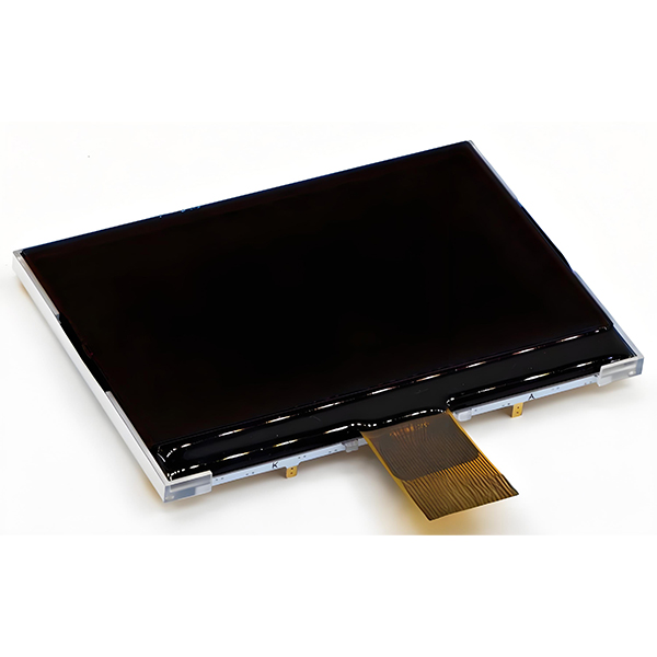
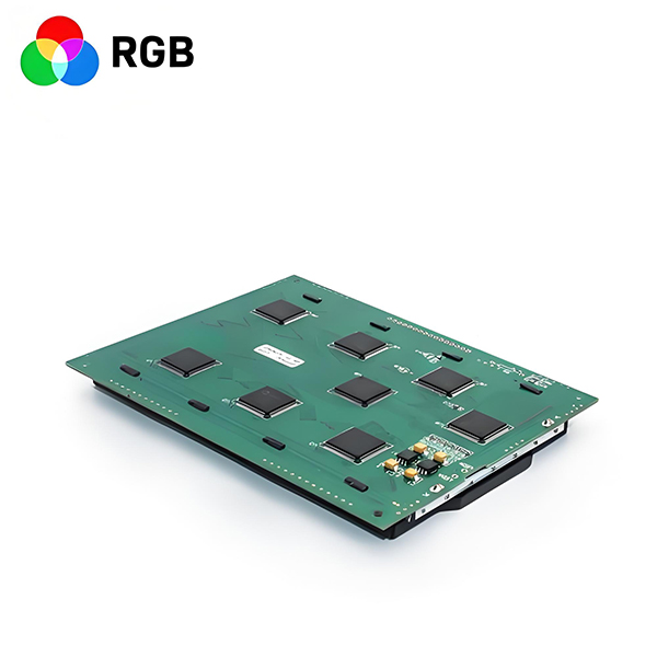
Exploded view of an LCD module highlighting the various components that must be properly integrated, knowledge that is essential for successful lcd screen replacement procedures.
Driver IC Attachment
Driver integrated circuits (ICs) are attached to the LCD cell to control the TFTs. These ICs receive digital signals and convert them into the analog voltages needed to drive each pixel. The attachment process uses advanced techniques:
COG (Chip on Glass)
Driver ICs are directly bonded to the glass substrate using anisotropic conductive film (ACF), which provides both mechanical bonding and electrical connection.
COF (Chip on Film)
Driver ICs are mounted on flexible film substrates that are then connected to the LCD cell, allowing for thinner display designs.
The driver IC attachment is a critical step where even minor defects can render the display non-functional. Proper handling techniques are essential, which is why lcd screen replacement requires specialized tools and expertise to avoid damaging these delicate connections.
Final Assembly and Testing
The completed LCD cell with driver ICs is combined with the backlight unit, and a protective cover glass is added. The module is then connected to a timing controller that processes input signals and coordinates the driver ICs.
Comprehensive testing follows, including checks for:
- Functional operation across all pixels
- Brightness uniformity and color accuracy
- Response time and viewing angles
- Power consumption under various conditions
- Reliability testing under temperature extremes
These tests ensure that only modules meeting strict quality standards proceed to final product integration. For lcd screen replacement markets, certified modules that pass these tests are preferred to ensure compatibility and performance.
LCD Manufacturing Process Improvements
The TFT LCD manufacturing process continues to evolve, driven by demands for higher performance, lower costs, and improved sustainability. These advancements benefit both manufacturers and end-users, including those requiring lcd screen replacement by providing better, more affordable display options.
Advanced Materials Development
New materials are continuously developed to improve display performance and manufacturing efficiency. For example, low-temperature poly-silicon (LTPS) TFTs offer higher electron mobility than traditional amorphous silicon, enabling faster response times and lower power consumption.
These material advancements have led to better display durability, reducing the frequency of lcd screen replacement in many applications. Additionally, new liquid crystal formulations provide improved viewing angles and faster response times, enhancing overall display quality.
Process Automation and AI
Increased automation and artificial intelligence (AI) integration have transformed LCD manufacturing. AI-powered inspection systems can detect defects with greater accuracy than human operators, improving yield rates and reducing costs.
Automated material handling and process control systems have minimized contamination risks and improved process consistency. These advancements have made high-quality displays more accessible, benefiting the lcd screen replacement market with more affordable, reliable options.
Sustainability Initiatives
Manufacturers are implementing more sustainable practices, including reducing energy consumption, using environmentally friendly materials, and developing recycling programs for end-of-life displays.
These initiatives not only benefit the environment but also create opportunities for more sustainable lcd screen replacement practices, including component recycling and material recovery from replaced screens.
Large Substrate Technology
The transition to larger glass substrates (from Gen 1 to current Gen 10.5) has significantly improved manufacturing efficiency. Larger substrates allow more displays to be produced per batch, reducing per-unit costs.
This economies-of-scale benefit has contributed to lower display prices across all market segments, making lcd screen replacement more affordable for consumers and businesses alike.
Future Trends in LCD Manufacturing
Looking ahead, several key trends are shaping the future of LCD manufacturing. Mini-LED backlighting technology is enhancing contrast ratios and enabling local dimming for better HDR performance. Quantum dot technology is improving color gamut and accuracy, bringing LCDs closer to OLED performance in certain aspects.
These advancements ensure that LCD technology will remain competitive in the display market for years to come, continuing to provide high-quality options for new devices and lcd screen replacement applications alike. As manufacturing processes become more sophisticated and cost-effective, LCDs will likely maintain their position as the dominant display technology in many market segments.
LCD Manufacturing Process Comparison
Comparison of relative complexity, cost, and defect rates across different LCD manufacturing stages, with implications for lcd screen replacement strategies and costs.
Summary of TFT LCD Manufacturing
TFT LCD manufacturing is a highly complex, multi-stage process requiring extreme precision, advanced materials, and sophisticated equipment. From array fabrication to module assembly, each stage contributes to the final display's performance and quality.
Continuous improvements in materials, processes, and automation have driven LCD technology forward, resulting in displays with higher resolution, better color accuracy, faster response times, and lower power consumption. These advancements benefit not only new device manufacturing but also the lcd screen replacement market by providing better, more affordable options for consumers and businesses needing to replace damaged or outdated displays.